


 Flexible Thinking: PCB Designers Still Wanted
 Connect the Dots: Five Best Practices for Designing Flex and Rigid-flex PCBs
 Tim’s Takeaways: Human Ingenuity and the Rigid-flex PCB
Growing Opportunities with 3D Printed Electronics
May 22, 2019 | Barry Matties, I-Connect007Estimated reading time: 1 minute
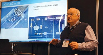
Dr. Kurt Christenson, senior scientist at Optomec, discusses the company’s Aerosol Jet technology, which eliminates the need for wire bonding by printing interconnects on 3D surfaces. Christenson also explores the current state of the technology and highlights the market segments and applications with the most to benefit from being able 3D print electronic components, such as resistors, capacitors, antennas, and transistors.
Barry Matties: Kurt, can you tell us a little bit about your company?
Dr. Kurt Christenson: Optomec makes additive manufacturing equipment. We have two divisions. One division makes a product called LENS that makes a melt pool in metal with a laser and then sprays powdered metal in to add material. When it cools and freezes, it follows the crystal structure, so we can repair a single crystal turbine blade or make full 3D metal parts. My part of the company makes a product called Aerosol Jet, which atomizes an ink. We don’t care what’s in the ink as long as we can make roughly three-micron droplets.
Then, we aerodynamically focus it down to a size where we can make from 10-micron lines to three-millimeter strips, depending on the need. My personal focus has been on connecting integrated circuits. We call it three-dimensional IC or 3D IC.
Matties: A while back, I did an interview with your colleague [Pascal Pierra] where we discussed printing on the wings of airplanes and such.
Christenson: Yes. That was the Aerosol Jet, which is my side of things. One of the things we do is print on aircraft wings. For instance, antennas on drone wings is a common interest that we get. A second would be heaters on specialty windows or headlight heaters.
To read the full version of this article which originally appeared in the April 2019 issue of Flex007 Magazine, click here.
Share on:


Suggested Items
Water Management in a Large Printed Circuit Board Manufacturer
04/15/2024 | Charles Nehrig, TTM TechnologiesTTM’s environmental management is grounded in its Environmental Statement and Environmental Policy, which promote measures that make for a more responsible environmental management process. Our management system helps TTM work toward minimizing its environmental footprint and increasing the sustainability of its operations. TTM monitors its environmental performance just as it monitors its operational performance, and provides the resources required to adhere to the Company’s environmental responsibilities.
Happy’s Tech Talk #27: Integrated Mesh Power System (IMPS) for PCBs
04/08/2024 | Happy Holden -- Column: Happy’s Tech TalkA significant decrease in HDI substrate production cost can be achieved by reducing the number of substrate layers from conventional through-hole multilayers and microvia multilayers of eight, 10, 12, and more to only two layers. Besides reducing direct processing steps, the yield will increase as defect-producing operations are eliminated. The integrated mesh power system (IMPS) was invented in the latter years of MCM-D use for thin-film fabrication. Those geometries fit today into our use of ultra HDI.
Trouble in Your Tank: Supporting IC Substrates and Advanced Packaging, Part 5
03/19/2024 | Michael Carano -- Column: Trouble in Your TankDirect metallization systems based on conductive graphite or carbon dispersion are quickly gaining acceptance worldwide. Indeed, the environmental and productivity gains one can achieve with these processes are outstanding. In today’s highly competitive and litigious environment, direct metallization reduces costs associated with compliance, waste treatment, and legal issues related to chemical exposure. What makes these processes leaders in the direct metallization space?
Indium Corporation Experts to Present at SEMI THERM
03/07/2024 | Indium CorporationIndium Corporation Global Account Manager and Senior Thermal Technologist Tim Jensen and Product Development Specialist for Thermal Interface Materials Miloš Lazić will present on thermal interface material (TIM) technology at SEMI-THERM, taking place March 25–28 in San Jose, California, U.S.
Indium Corporation to Showcase Proven EV Products and High-Reliability Alloys at Productronica China
02/28/2024 | Indium CorporationAs a materials pioneer and trusted partner in electric vehicle (EV) and e-Mobility manufacturing, Indium Corporation is proud to showcase its high-reliability alloys and soldering solutions at Productronica China, March 20-22, in Shanghai.