


 Flexible Thinking: PCB Designers Still Wanted
 Connect the Dots: Five Best Practices for Designing Flex and Rigid-flex PCBs
 Tim’s Takeaways: Human Ingenuity and the Rigid-flex PCB
The GraftWorx Fluid Management Patch Story
May 31, 2019 | Anthony Flannery, GraftWorxEstimated reading time: 4 minutes
The GraftWorx vision is to connect patients to clinicians with clinical data that will have a meaningful impact on their care. Our first application is to monitor patients with end-stage renal disease (ESRD) or kidney failure using a wearable device called the SmartPatch that records numerous clinical cardiovascular metrics. The SmartPatch communicates via BLE 4.2 to a medical grade data relay that transmits the data compliant with PHI and HIPAA over a cellular network into our secure cloud. The entire system works seamlessly without any intervention by either party to put real-time, clinical data where it can be integrated into care management pathways to reduce the incidence of hospitalizations and improve the quality of care for patients with chronic conditions.
Our solution architecture is focused on the design of a comfortable, sophisticated, ultralow power device that a patient can wear for a week in a “forgettable” manner—quite a challenge! Working with the right electronics vendor as a partner to build our first clinical devices has been critical to the successful execution along our product development timeline. We evaluated a long list of potential partners before choosing Lenthor Engineering in Milpitas, California, as our fabrication partner.
On a technical level, the device itself was challenging to create. First were the requirements on the board itself. Because comfort is so important for our wearable product, we wanted to minimize the rigid areas required for bonding electronics and maximize flexibility in other regions. We also wanted to avoid the complexity and extra cost of a rigid-flex solution. To meet these needs, we partnered with Lenthor to spec out and develop a rigidized flex solution that used thicker blank cores within the 4-layer region of the populated “islands” of the board. The tether region was an extremely flexible thin 2-layer region with minimal coverlay. The flexible inner two layers ran contiguously across the board, connecting the rigidized islands without changing materials (Figure 1).
Figure 1: Cross-section of layers in the customized PCB process for the GraftWorx wearable. The blank cores provided sufficient rigidity to meet reliability requirements while the thinner tether regions were extremely light and flexible, enabling maximum comfort for the patient.
Armed with a solid solution for the flex board, the next challenge involved assembly and sensors. One thing almost all wearables have in common is the need for some form of sensor interface to the real world. The GraftWorx device measures hemoglobin, SpO2, heart rate, temperature, and volumetric flow with a powerful fusion of 11 sensor data streams. Unfortunately, because of this interface, sensors typically have some form of vulnerability beyond standard ICs. Our MEMS accelerometer can be damaged by excessive shock from a pick-and-place machine. The microphone has a port open to atmosphere, which exposes the delicate internal diaphragm. It can be damaged by particles, fluid, and excessive percussive pressure changes. The optical sensors have transparent windows that can be damaged by aggressive mechanical handling.
Solutions in a high-volume assembly process can be found in the application notes from the component manufacturers and have been developed from experience with other products, such as smartphones. These can include adjustments to a standard assembly process, such as tip material choice, pick-and-place parameters, use of a no-clean flux, and reflow profile. Because each type of sensor can have different sensitivities, all must be reviewed to determine if they can be accommodated in a single pass with regular ICs, or if they are going to require an additional custom pass. Without a willingness to review what may be novel requirements for assembly and adjust and requalify a standard process, sensor components will be damaged, and yields will suffer.
Once fully assembled, we had a challenge with our battery. Our wearable is a single-use device. To achieve an acceptable lifetime, we engineered a very efficient power management scheme with hardware and firmware that can achieve a quiescent current of 50nA as well as respond to outside stimuli by waking up and performing tasks. The boards had to be tested and programmed with this power management firmware before solder attach of the primary cell, or the battery would start to power the circuit. In sufficiently high volume and with a mature code base, we could have had our firmware image pre-loaded into our microcontroller, but for this stage, the lead time and cost were not supportable. Neither did we have a production worthy pogo or bed-of-nails fixture to test and program the board. Lenthor’s flexibility enabled the GraftWorx engineers time to test and program the assembled boards in their facility with a prototype fixture and system just before the final battery attach.
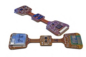
Figure 2: Final electronics assembly for molding into the GraftWorx SmartPatch.
The resulting electronics assembly shown met all of the requirements wonderfully (Figure 2). The tethers were flexible enough that they added no significant stiffness to the Smart-Patch. Spatial packing of the electronics was very efficient. Asymmetric through holes were designed into the edges of the board to facilitate mounting in a pogo pin test fixture. The electronics are a completely self-contained remote monitoring platform. Once encapsulated, there are no physical connections with the outside world. All functions, including testing, data telemetry, status monitoring, parameter updates, and over-the-air-programming (OTAP), are done wirelessly.
As a cash-strapped startup, it was important to manage some of the risks during development. There is always a tradeoff between the efficiency and cost per unit of a large batch run and the risk of committing those resources to a design that had yet to be verified. Before running the first lot at Lenthor on the customized platform, a small quantity was run through a standard, quick-turn process on FR-4. Being completely rigid, these units were not suitable to be molded and placed on a patient’s arm, but running a relatively inexpensive, quickturn version let us debug the schematic and layout.
To read the full article, which appeared in the April 2019 issue of Flex007 Magazine, click here.
Share on:


Suggested Items
AIM to Highlight NC259FPA Ultrafine No Clean Solder Paste at SMTA Wisconsin Expo & Tech Forum
04/18/2024 | AIMAIM Solder, a leading global manufacturer of solder assembly materials for the electronics industry, is pleased to announce its participation in the upcoming SMTA Wisconsin Expo & Tech Forum taking place on May 7 at the Four Points by Sheraton | Milwaukee Airport, in Milwaukee, Wisconsin.
Hentec/RPS Publishes an Essential Guide to Selective Soldering Processing Tech Paper
04/17/2024 | Hentec Industries/RPS AutomationHentec Industries/RPS Automation, a leading manufacturer of selective soldering, lead tinning and solderability test equipment, announces that it has published a technical paper describing the critical process parameters that need to be optimized to ensure optimal results and guarantee the utmost in end-product quality.
Empowering Electronics Assembly: Introducing ALPHA Innolot MXE Alloy
04/16/2024 | MacDermid Alpha Electronics SolutionsIn the rapidly evolving electronics industry, where innovation drives progress, MacDermid Alpha Electronics Solutions is committed to setting a new standard. Today, we are pleased to introduce ALPHA Innolot MXE, a revolutionary alloy meticulously engineered to address the critical needs of enhanced reliability and performance in modern electronic assemblies.
New Book on Low-temperature Soldering Now Available
04/17/2024 | I-Connect007I-Connect007 is pleased to announce that The Printed Circuit Assembler’s Guide to… Low-temperature Soldering, Vol. 2, by subject matter experts at MacDermid Alpha Electronics Solutions, is now available for download.
Inkjet Solder Mask ‘Has Arrived’
04/10/2024 | Pete Starkey, I-Connect007I was delighted to be invited to attend an interactive webinar entitled “Solder Mask Coating Made Easy with Additive Manufacturing,” hosted by SUSS MicroTec Netherlands in Eindhoven. The webinar was introduced and moderated by André Bodegom, managing director at Adeon Technologies, and the speakers were Mariana Van Dam, senior product manager PCB imaging solutions at AGFA in Belgium; Ashley Steers, sales manager at Electra Polymers in the UK; and Dr. Luca Gautero, product manager at SUSS MicroTec Netherlands.