


 Flexible Thinking: PCB Designers Still Wanted
 Connect the Dots: Five Best Practices for Designing Flex and Rigid-flex PCBs
 Tim’s Takeaways: Human Ingenuity and the Rigid-flex PCB
Decreasing Bend Radius and Improving Reliability- Part III
December 18, 2019 | Kelsey Smith, All FlexEstimated reading time: 1 minute
Application: Design guidelines to improve the flexibility and reliability of flexible circuits.
Most issues that arise with flex circuits can be eliminated in the early stages of the design phase, and special planning must occur when the circuit is required to bend. Many novices will design a circuit that calls for bending the flex in too tight of a bend radius, which can cause damage to the circuit and lower the reliability of the end product. This is the third and final installment in a series of articles that will focus on the seven key aspects to consider when designing for maximum durability and maximum “flexibility." It is important to know that because flexibility is a relative term this study will instead use the term reducing bend radius. Below are three of the seven design strategies, please see Part I and Part II for more tips!
5. Apply strain relief at transition areas from stiffener to flex.
- Stiffener material is common in flex circuit designs that have soldered components. While this rigid material is necessary for the soldered components, it can cause reliability issues during installation when the flex is bent at the stiffener location toward the stiffener.
- If the flex material will be bending toward the stiffener, it is highly recommended that an epoxy bead of Ecobond 45 be applied.
6. Ensure vias are located at least .050” away from bend zones.

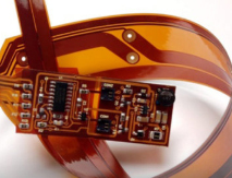
Fig. 1 - Examples of a flex circuit with a bend radius and a plated through-hole.
7. Always put a 3D representation of your bend to install configuration on your drawings.
- Many problems can be avoided by informing your flex circuit vendor what the final configuration is going to be once used, this enables them to evaluate for potential bend radius issues.
- Most flex circuit drawings are only 2D. By showing a picture of the final configuration you are encouraging the discussion regarding materials, discussion about minimum bend radius and letting the flex vendor raise any concerns before build.

Fig. 2 - Examples of a 3D drawing of a flex circuit.
Share on:


Suggested Items
Real Time with... IPC APEX EXPO 2024: Exploring IPC's PCB Design Courses with Kris Moyer
04/18/2024 | Real Time with...IPC APEX EXPOGuest Editor Kelly Dack and IPC instructor Kris Moyer discuss IPC's PCB design training and education offerings. They delve into course topics such as design fundamentals, mil/aero, rigid-flex, RF design, and advanced design concepts. They also highlight material selection for high-speed design, thermal management, and dissipation techniques. The interview wraps up with details about how to access these courses online.
Cadence Unveils Palladium Z3 and Protium X3 Systems
04/18/2024 | Cadence Design SystemsThe Palladium Z3 and Protium X3 systems offer increased capacity, and scale from job sizes of 16 million gates up to 48 billion gates, so the largest SoCs can be tested as a whole rather than just partial models, ensuring proper functionality and performance.
Signal Integrity Expert Donald Telian to Teach 'Signal Integrity, In Practice' Masterclass Globally
04/17/2024 | PRLOGDonald Telian and The EEcosystem announce the global tour of "Signal Integrity, In Practice," a groundbreaking LIVE masterclass designed to equip hardware engineers with essential skills for solving Signal Integrity (SI) challenges in today's fast-paced technological landscape.
On the Line With... Podcast Talks With Cadence Expert on Manufacturing
04/18/2024 | I-Connect007In “PCB 3.0: A New Design Methodology: Manufacturing” Patrick Davis returns to the podcast to talk about design rules. As design considerations become more and more complex, so, too, do the rulesets designers must abide by.
Designing Electronics for High Thermal Loads
04/16/2024 | Akber Roy, Rush PCB Inc.Developing proactive thermal management strategies is important in the early stages of the PCB design cycle to minimize costly redesign iterations. Here, I delve into key aspects of electronic design that hold particular relevance for managing heat in electronic systems. Each of these considerations plays a pivotal role in enhancing the reliability and performance of the overall system.